How to Sync an LED Pixel Strip with MIDI Song Files
Instructions & Code/Sketches
About this Project Supplies & Tools Needed Soldering & Assembly
Programming Microcontroller Using MIDI Software Main Page Contact
About this ProjectThe best way to understand what this does is to watch some videos. Here are some with classical music: |
|
|
|
|
|
|
|
|
Colors correspond to notes as follows:
Colors can vary with different LED's and cameras, possibly monitors, and the colors can be adjusted in the code or changed completely to your own preferences. This project can be used with other types of music, if the songs are available in MIDI form. A search engine can often find numerous MIDI files from a variety of genres. The LED response is automated and based off the notes of the music. You do not need to program every light turn-on and it's timing because that is handled in the code. In its current form, there is no separate display for percussion. However, there are 2 forms of percussion sketches elsewhere on this web site. Those can be adapted to run another display or dedicated LED's on the same display, with some code editing. Future versions of the code will likely include something different for percussion, when I have some more time. The software used in this tutorial does not work with MP3's. To use this project with MP3's requires MP3-to-MIDI conversion and software that can simultaneously play an MP3, read a MIDI file, and send USB MIDI. This is unexplored and untested at this time. If there's enough interest, I might sell kits or finished products in the future. At the moment, this is just a how-to page for motivated DIY people. This tutorial uses an APA102 LED strip, however the code can be adapted to use other types of LED pixels, also known as addressable LED's. It's important to use a libary that uses DMA (Direct Memory Access). See this for more details. This sketch has example code of how to use Neopixels (WS2811/WS2812/WS2812B) on a Teensy with a DMA-based library. The APA102 LED's are easier to film without aliasing and transfer data faster. Neopixels are less expensive. |
|
Supplies & Tools NeededHere's a list of supplies and tools needed. Most of these can be purchased from hobbyist web sites like Sparkfun and Adafruit. Supplies
Tools
|
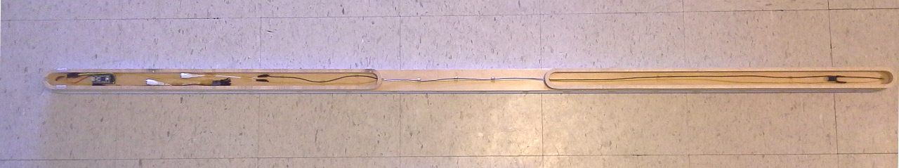
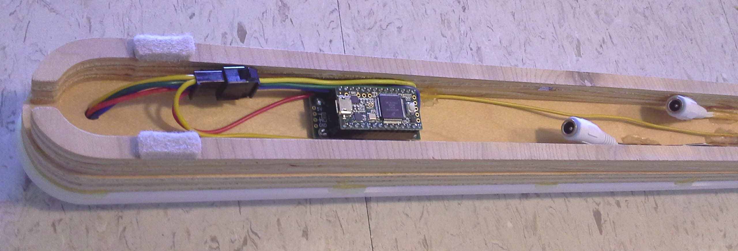
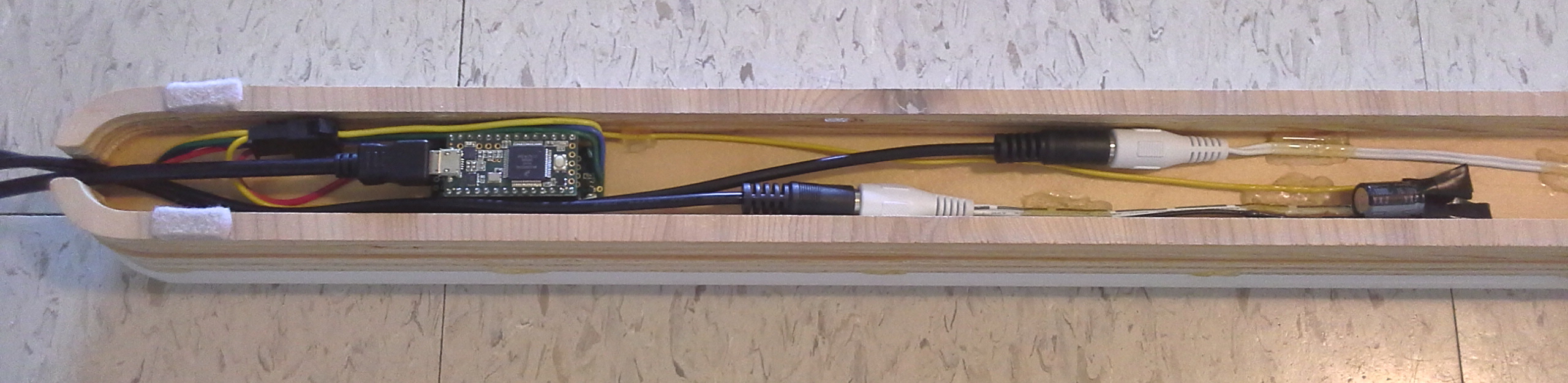
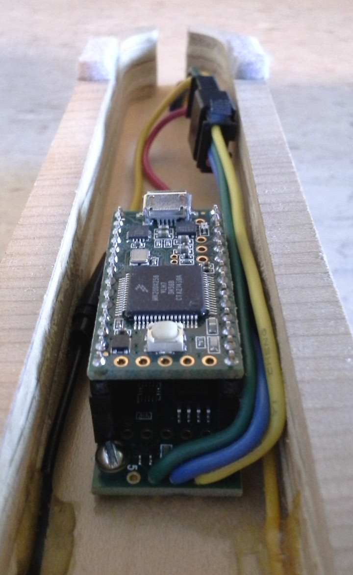
Soldering & AssemblyThis is potentially one of the easiest projects on this web site because it doesn't require building a custom circuit on a prototyping board. The details of your build can, however, affect the complexity. Photos are below. There is no particular order in which to do anything, besides the obvious. I've included some important notes with some of the photos. On each photo you can click to enlarge and see more details.
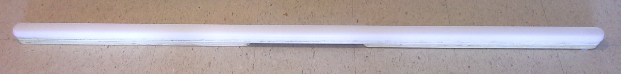
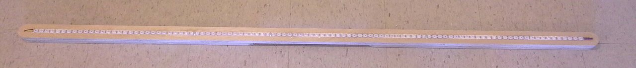
My build uses scraps of translucent acrylic. Since it may be difficult to order translucent acrylic in small quantities, I recommend using a channel and diffuser meant for LED strips. Amazon and eBay have some really good deals:
It's important to have enough distance to the diffuser to properly mix all 3 component colors (red, green, blue) but not so much distance that each LED blends into the nearby LED's. I found 3/8" to be a good distance between the diffuser and the mounting surface of the LED's, but the best distance may vary with different diffuser materials and thicknesses. I used dabs of Loctite GO2 gel glue to hold the acrylic to the plywood. The 2 acrylic pieces are bonded together with Acrifix 117. The thin solvent version of Weld-On seems to be a more common acrylic adhesive but also contains methylene chloride which generates more toxic fumes.
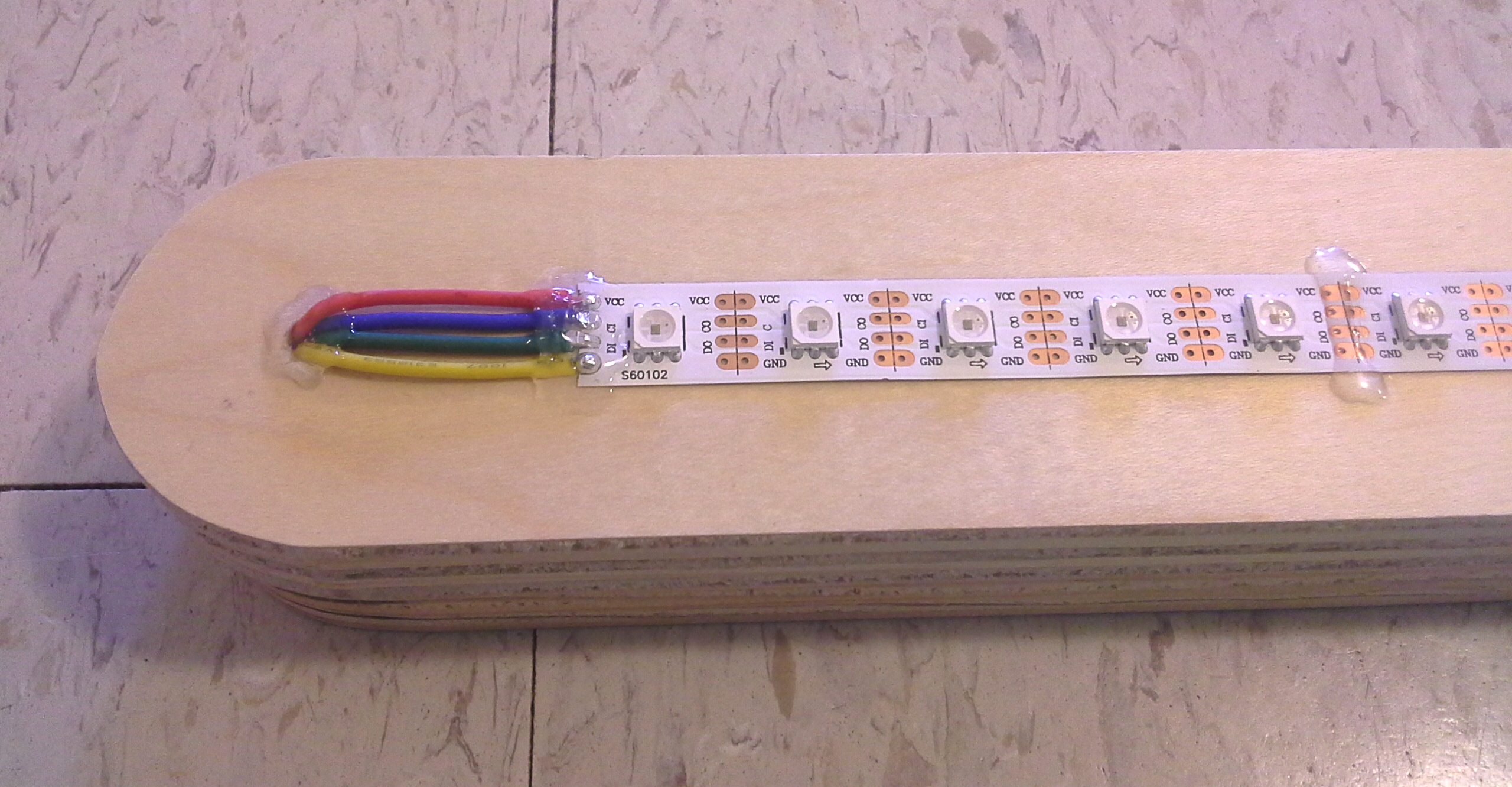
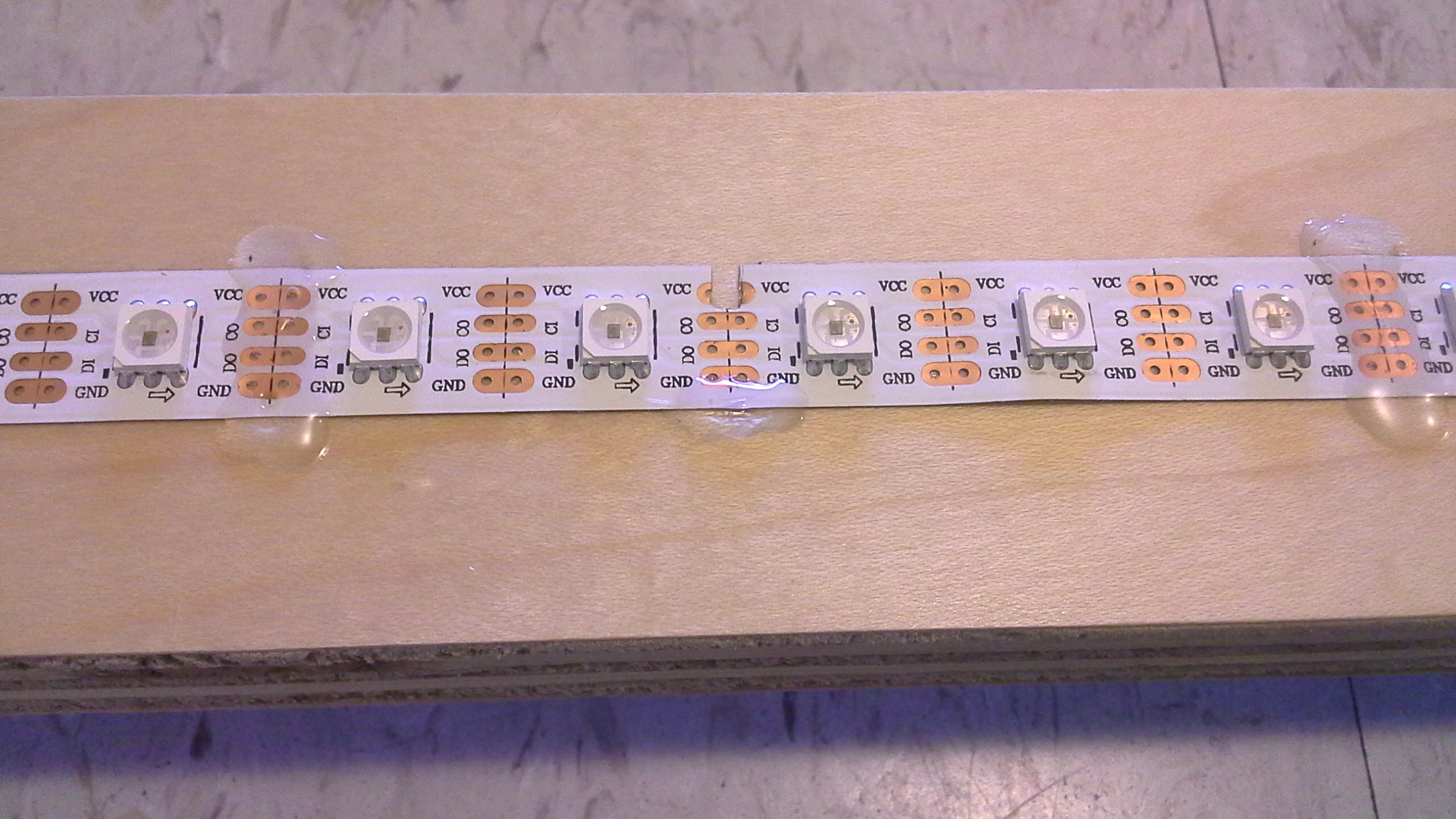
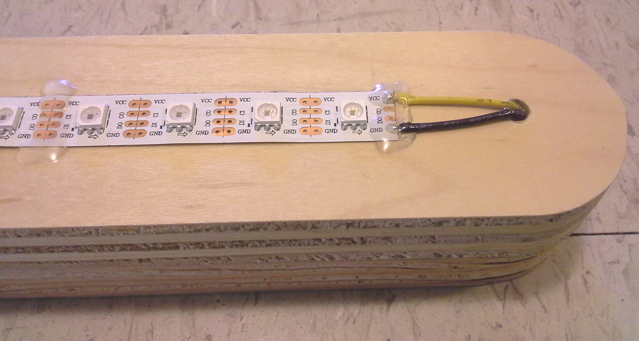
Colors may vary with different products, but any APA102 strip will have these 4 connections. Other types of LED pixels and addressable LED's can be used. However, it's important to use a DMA-based library. See this page for more details. This sketch has example code of how to use Neopixels (WS2811/WS2812/WS2812B) with DMA on a Teensy.
To solder wires to LED strips, the soldering iron will have to be turned up hotter than you normally do for circuit boards. With lead-free solder, 800 °F is a good temperature (750 °F for leaded) and don't spend too much time to avoid overheating the LED chips and IC chip inside, but there is some cooling across the copper traces and wire so it's not like you're directly touching a part with the iron. For an iron that does not have a temperature setting, a 25W iron is probably fine for leaded solder and 40W for lead-free. The shape of the tip makes a difference (sharper thinner points deliver less heat, blunter tips deliver more heat) as well as the airflow of a fan. A 60W iron can be cooled with a fan, and a 25W iron can get hotter by letting it sit for awhile between solders. Using a fan to suck away the fumes usually won't cool the iron as much as blowing air onto the iron. Avoid using solders with antimony or silver because they are more difficult to work with and have higher melting temperatures. It helps to hold the wire down with a weight or an alligator clip. Even better: cross-locking tweezers. The stripped end should be touching the copper pad. Apply a little solder to the iron tip first to help transfer the heat, then touch the bare wire and copper pad, then feed more solder (experiment with the speed of feeding the solder). As soon as it sticks to the copper pad, pull away the solder, then pull away the iron afterwards.
If you've never used Teensy before, here's a guide that can help:
Cords can be hidden inside a wall using an electrician's snake, also known as fish tape, available at a hardware store. The thin ones that are 1/4" wide are easier to use than the thick ones that are 1/8" wide. After the snake is pushed through both holes that you've drilled, you can tape cords to the end (stagger the plugs to keep it low profile) and pull through the wall. |


Programming Microcontroller (Using Teensyduino)The software for the Teensy can be downloaded from here, and there are instructions for Windows, Mac OS, and Linux. It modifies the Arduino software to also work with Teensy devices, so whatever computer you are using, you'll need to install a compatible version of Arduino software first. Here are the sketches to load onto the Teensy: They have the same general code, but one has settings for piano, the other has settings for organ. To use a sketch: download, unzip, then run Teensyduino and open the file with the same name as the folder. Click on the a_global tab to edit settings. Time delay must approximately match buffering time of MIDI software and can include additional milliseconds to account for distance from speakers. There are many other settings in this a_global tab. The fade up and fade off features use bit-shifting (powers of 2). "mS" means milliseconds.
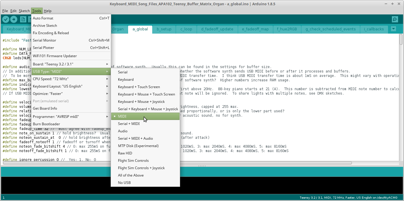
Compile with MIDI selected. This is necessary for software to recognize the Teensy as a MIDI device. See screenshot below:
In it's current form, this sketch works best with Teensy 3.2, although it may run on Teensy LC if you don't need much buffering time or number of notes buffered. It's not the most efficient use of RAM, so I'm rewriting the code. A future release of this will likely work fine on Teensy LC, and I'm eliminating the bitshifting and replacing with division for ease of use and more customization. A future release that includes a dedicated display/response for percussion and has different displays or responses to each instrument type would likely require using the Teensy 3.2 and not work with Teensy LC. |

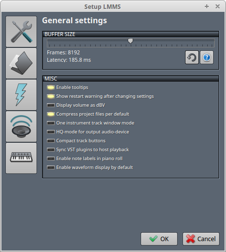
Using MIDI Software (LMMS)The LED setup should work with any software that can send USB MIDI and play sound at the same time. This includes free software as well as commercial software like Ableton. For this tutorial, we're using LMMS. It's formerly known as Linux MultiMedia Studio and despite the name, it is available for Windows and Mac's, not just Linux. It's also free and open source. You'll want to install LMMS on a laptop to avoid potentially having a ground loop which creates annoying hum in the speakers. If you must use a desktop, there are some USB ground-lifting devices sold on the Internet that can help with that issue. Ground-lifting the power supply (3-prong to 2-prong adapter) is unsafe and not recommended. To get started with LMMS, you'll need to adjust the settings. Top Menu: Edit > Settings, then you'll see a pop-up window that contains 5 icons on the left side of the new window. Changes to settings take effect only after restarting LMMS.
The buffer size has to be large enough to have good sound quality. If you're not connecting a musical keyboard to your computer, then there's no concern about latency. The Teensy can compensate for the latency by adjusting the number in the sketch to match the latency shown in the settings window. If the speakers are far away you can also add 0.89 milliseconds per foot of distance (2.9 milliseconds per meter). Click on the folder icon, and at the bottom of this menu you can select a soundfont. This will need to be downloaded from another source because this is not included with LMMS. I used the FluidSynth sound font, also available for free. I used the command line apt-get method of installing in Linux Mint, then located the .SF2 file within the install and used that file with LMMS. The filename is called "FluidR3_GM.sf2". At this time I can't find a reliable and reputable source for downloading this directly, and I don't see the license file. This might be the same file:
Here's a direct download from a newer version of FluidSynth:
Here's another soundfont that someone posted for the purpose of direct downloading:
What's the best soundfont? There are plenty of opinions on the MuseScore forum as well as links to other soundfonts:
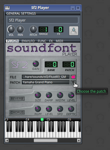
After you've installed a soundfont, click on the speaker icon. You'll have to select an audio interface. I've used ALSA and SDL in Linux. You'll have to experiment and see what works well on your computer. You might have to click on the keyboard icon and experiment with the MIDI settings to send USB MIDI. You'll want to close LMMS and re-open each time to test settings. To play a song, you'll need to import a MIDI file using the menu option Project > Import... and then select the MIDI file that you have downloaded from somewhere or created yourself. The instrument can be selected by clicking on the "SF2 Player" button to the left of the volume knob for the track.
A new window will pop up. Click on the wrench icon to the right of where it says "Patch" and whatever instrument is currently selected.
To send USB MIDI to the Teensy, you'll have to click on the gear symbol next to each track and select MIDI > Output and then select the Teensy which should show up. If it does not show up, then you may have forgotten to compile as a MIDI device when loading the code.
After this, you can click the Play button (triangle). If sound and lights work, then it's all ready to enjoy and play more music. Otherwise experiment with settings and restart LMMS to try again. LMMS may have occasional bugs that have to be worked around by trying things. Sometimes when I load a MIDI file it says the soundfont failed. When this happens I have to re-select the soundfont file by clicking on "Sf2 Player" for each track and re-selecting the SF2 file and instrument in the pop-up window. If the Teensy is disconnected and then re-connected later via USB cable, you may have to re-select the MIDI output for each track. |


Main Page
e-mail: lights4music at (@) lights4music dot (.) com