MIDI-to-DMX with Arduino & Teensy
Instructions & Code/Sketches
How to Use Arduino How to Use Teensy Download Code USB MIDI
Mounting inside a Box Using LED Pixels Videos Contact
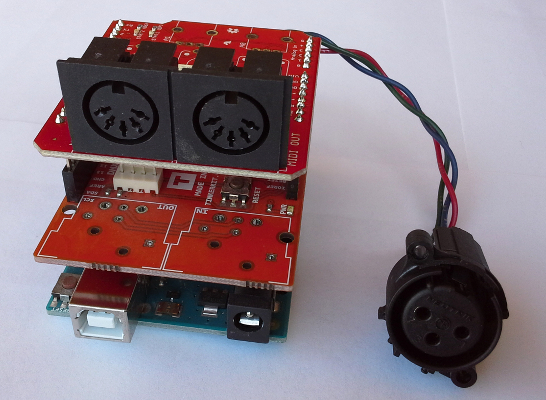
Arduino with MIDI and DMX Shields
Update: It appears that this DMX shield is discontinued, but a few places have small quantities left such as Amazon. See notes below about the Conceptinetics DMX shield which appears to be a current product. The easiest way to do this is to stack a MIDI shield and a DMX shield onto an Arduino, assuming you're using 5-pin MIDI (for USB MIDI see below). In the photo above, an Arduino Uno is used with the Sparkfun MIDI shield and Tinkerkit DMX shield. The MIDI shield has tall headers, and the DMX (XLR) connectors are not soldered onto the shield so it's possible to stack the shields. To wire the XLR connector to the terminal blocks of the DMX shield, you'll need to do an image search for "DMX pinout" diagrams for either 3-pin XLR, 5-pin XLR, RJ45 with ESTA pinout, or RJ45 for Philips lights, depending on what type of lights you are using. Note that 3-pin XLR connectors are wired differently for microphone purposes, and pay attention to whether the diagram is showing the front or rear of the connector. In the photo above, I used a Neutrik brand 3-pin XLR connector. It may be helpful to remember that DMX cables are wired with parallel connections, so the pin numbers swap left-right when you look at both ends at the same time. In contrast, RJ45 cables (cat5, cat5e, cat6, cat7) are wired with left-right swapped connections along the length of the cable, so the pin numbers are identical when you're viewing both ends. The same is true of MIDI cables. If you plan to place inside a box, it's easiest to not solder the MIDI connectors to the shield and send the wires to panel mount (chassis) 5-pin DIN connectors such as those by KobiConn or Switchcraft. If you need MIDI THRU, be sure to solder for MIDI THRU. Keep the hardware serial selected to use the code below, and use the Run/Program switch as needed for loading new sketches. I have not tested software serial for this project, so that may or may not work. This setup will work with Program 1 below but will likely not work with the other programs due to RAM limitations. I have used Arduino Uno with keyboard for 8 lights only, so programs 3 and 4 will probably work with 8 lights on the Uno if you edit the code to use a small number of keys. Program #2 for 8 lights might work on Arduino Uno if you modify code to reduce RAM usage, but I haven't tested that. Programs 2, 3, and 4 might work with the Arduino 101 or Mega, but I haven't tested these. And they might work with a Teensy 3.2 and Teensy-to-Arduino adapter using DMXsimple library, but I haven't tested this either. Avoid using the Arduino Zero or Teensy LC with the MIDI shield because they are not 5V-tolerant, so a MIDI shield designed to run on 5V could damage the RX pin. The same is true if you are receiving DMX which is not part of these programs, but some DMX shields are capable of receiving. Whatever MIDI and DMX shields you use, they probably can't use the same hardware serial, even though sending DMX uses TX and receiving MIDI uses RX, because the baudrates are different. The DMXmaster/DMXsimple library doesn't use hardware serial and allows for pin choice, and the Uno only has 1 hardware serial which is used for MIDI in Program 1 below. Whichever Arduino or Teensy you choose, it's important to pay attention to which pins are being used by the shields. If you use the Conceptinetics DMX shield instead, you'll want to place that on top because it comes pre-soldered, and the MIDI shield will need stackable headers, and you can't solder the MIDI (DIN) connectors to the shield. You'll have to select TX-io on the DMX shield and select pin 4 in the code. Although I have not tested this setup, it should work. Pin 2 might need to go HIGH to select transmit mode on the shield. |
Teensy LC/3.2 with Homemade Circuits
Update: here's a product that would probably work with Teensy:
To use with Teensy, you'll have to build a couple basic circuits. Here's a good reference on MIDI: https://www.pjrc.com/teensy/td_libs_MIDI.html
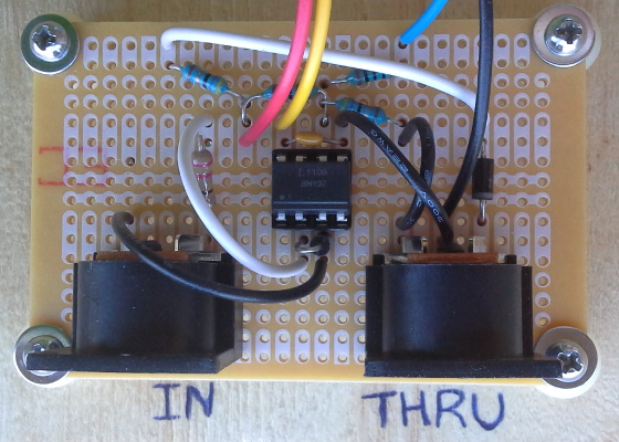
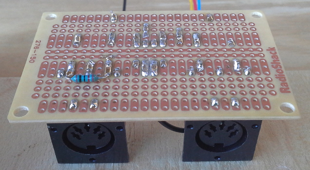
But the resistors need to be adjusted for 3.3V as mentioned on the page, not for 5V as shown in the diagram which is for the older Teensy 2.0. If your optoisolator contains a photodiode + transistor, it most likely has enough pull-down to be used for MIDI THRU without the need for a buffer, as long as the pullup resistor is not too strong. I did this with a 6N137 in the photo above and also the 2 photos below. Here's another circuit for MIDI IN:
http://codeandlife.com/2016/01/17/midi-to-usb-adapter-with-teensy-lc/
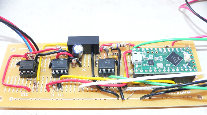
Here's a MIDI circuit that I built more recently:
When I have some more time I'll label the resistors and draw the connections. The diode and resistor near the MIDI THRU connector are optional and may provide some protection against wrong connections and equipment failures, maybe static discharge if the diode is rated for very high voltages or if a 5V zener diode is added in parallel to the 10k resistor. To see where the wires connect, you can look at the photos in the last section below. To use Serial1 (DMX programs), connect the blue wire to Pin 0. Pin 7 is for Serial 3 which is used in the Neopixels programs. A basic circuit for DMX is here: https://playground.arduino.cc/DMX/DMXShield That wiring diagram is strange because it activates the transmitter and receiver at the same time, but it does work. It also works with 3.3V processors because that voltage is high enough to be interpreted as high by the IC chip, even though the chip runs at 5V. Programs 2, 3, and 4 use Serial3 TX which is pin 8 on Teensy 3.2 and Teensy LC. The DMX circuit in the first photo is similar to the send portion of this isolated circuit: http://www.mathertel.de/Arduino/DMXShield.aspx
|
Code/SketchesHere are the 4 general programs with some variations:
To use a program it has to be unzipped, then open the file with the same name as the folder. You'll see the other files in the tabs to the right. The comments in the main tab explain how to change settings, and there are comments in the beginning of some tabs. These sketches have fadeoffs (all programs), color changes (1 & 2), color mixing (2, 3, & 4), fast fadeup (3 & 4), and a variety of other options. Most of the other MIDI-to-DMX sketches on the Internet are turn-on-turn-off with limited features. My opinion is that the features of my sketches significantly enhance the audio-visual experience, and it's likely that a live audience would agree. Some of these features are difficult to fully experience by watching a video, even at 60 frames per second, and are best appreciated by seeing it in person. Program 1 has been tested with Arduino Uno. The others have been tested with Teensy LC and very likely work with Teensy 3.2 also. To use with Teensy, you'll need to install Teensyduino after installing Arduino software. The MIDI library is included, and the DMX commands are done without a library in programs 2, 3, and 4. Program 1 uses the DmxMaster library (for Arduino only) which can be substituted with the DmxSimple library which is included in Teensyduino (if using Teensy 3.2, not Teensy LC), or you can use the same serial commands used in the other programs. For use on Arduino, you'll need to download the DmxMaster library by Tinkerkit and the MIDI library by 47 Effects. You'll also need to include and uncomment this line in the "a_global" tab: MIDI_CREATE_DEFAULT_INSTANCE(); For older versions of Teensyduino, comment out or delete that line. Newer versions of Teensyduino require that line. The MIDI library is included with Teensyduino and does not require another download/install. Programs 2, 3, & 4 use direct serial commands for DMX. These can be replaced with DmxSimple/DmxMaster commands (not compatible with Teensy LC) to use on almost any pin. The trade-off is that you won't have the buffering of hardware serial which is unlikely to make a noticeable difference in latency with these sketches. This could, however, become an issue with sketches that require more calculation time and have a large number of DMX channels and large number of simultaneous MIDI commands. Programs 3 & 4 have the same general code but with different constants in the a_global tab. Visually, they are quite different. |
USB MIDITo use USB MIDI instead of 5-pin MIDI, obviously you don't need a MIDI shield or a special circuit because there's already a USB connector. Instructions depend on which processor you're using:
|
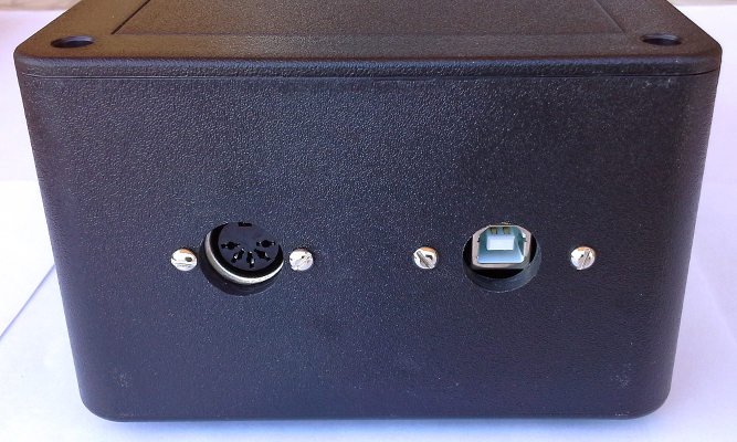
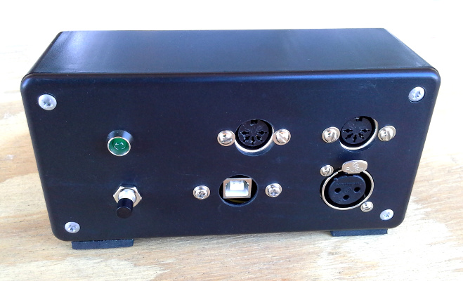
Mounting Inside a Box
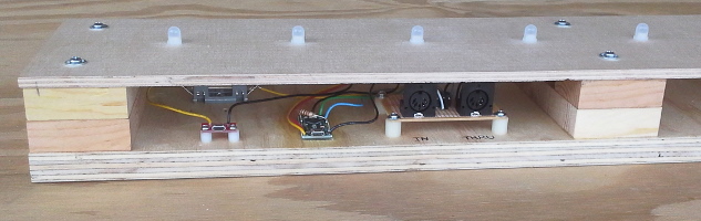
Here are general drill templates in PDF and SVG form: The SVG files can be edited in Inkscape which is free and open source. It's a good idea to do a visual check with the parts before marking with a nail or centerpunch. Some printers may print a little too small or large. You can compensate for this by using the edge of the lines or by modifying the SVG file (or more properly, by callibrating the printer if possible). The parts are metric, so its best to use metric machine screws and corresponding drill bits for close fit holes. I have been able to use #2 and #4 machine screws here in the USA and just the common drill bits found in a small drill index. If drilling by hand, spade bits tend to drift in plastic. You can see that a little in the photo above, but it still works fine as long as there's not too much drift. If I were to do it again, I would use a drill press. For live shows on the road, you probably want a heavy duty box like that shown in the photo above, and it may be nice to add a rotary mode selector switch and possibly a DMX input to mix with or switch between other lighting controllers. But if you just want one program to run the entire show that really keeps things simple. If using a Teensy, you need to wire the Program pin and ground to a normally open (N.O.) momentary push button. I also added an indicator LED to the prototype below, which can be useful for debugging and general problem-solving.
|
Using LED Pixels (Addressable LED's)
Sometimes you can just replace all the DMX commands with library commands for the LED strip or LED modules you are using. For APA102 LED strips and probably other 4-wire pixel strips, this works with the FastLED library because it uses hardware SPI. For Neopixels (WS2811, WS2812, WS2812B) and other 3-wire LED strips/strings it's a little more involved. The Adafruit Neopixel library and FastLED library for Neopixels will disable millis() and serial commands (used by MIDI library) any time LED data is sent, and therefore the programs here cannot be adapted to use those libraries unless you are using 10 or fewer LED's per strip/string and don't care about timing accuracy of fadeoffs. Instead, you need to use a DMA-based (direct memory access) library that does not disable interupts while the LED data is being sent. For Arduinos with AVR processors, see this link:
For Teensy, you need to use this library which is not already included in Teensyduino 1.41 but will likely be included in future releases:
Many of the discrete MOSFET-based level converters are too slow to use with LED pixels. The IC-based converters are usually faster. To use the on-board level-converter of Teensy LC, connect a 1K resistor from pin 1 to pin 17 as seen in this photo:
It's a good idea to connect a 330 or 470-ohm resistor between the level converter output and the data input to the first LED. Adafruit and Sparkfun also recommend putting a 1000µF cap between 5V and GND (I do this at the first LED), and if soldering individual LED's that are not part of a strip or string, adding a 0.1µF ceramic cap between 5V and GND at every LED. The OctoWS2811 library will also work but is overkill for most projects that only need 1 LED strip or string. With a lot of LED's, there is the advantage of faster refresh rates at the expense of using more RAM and more pins. The code here can be adapted to other creative displays, and this may be easier than starting from scratch. With a somewhat large number of LED's, it's possible to not have to share lights with multiple notes. With very large amounts of LED's, each note could create an animation across many LED's. Here are some videos from a recent project that uses APA102 LED's, USB MIDI, and MIDI song files. Instructions are on this other page. |
Watch Videos on Main Page
e-mail: lights4music at (@) lights4music dot (.) com